
Robot Console and Calibration
A walk-through of the class day where students connect their robot to the laptop, run the initial calibration, and put the calibration values into their first MakeCode program.
1. Get a laptop and the robot ready
Get a laptop and your robot. Log in to the laptop and set the robot up next to it for the initial calibration.
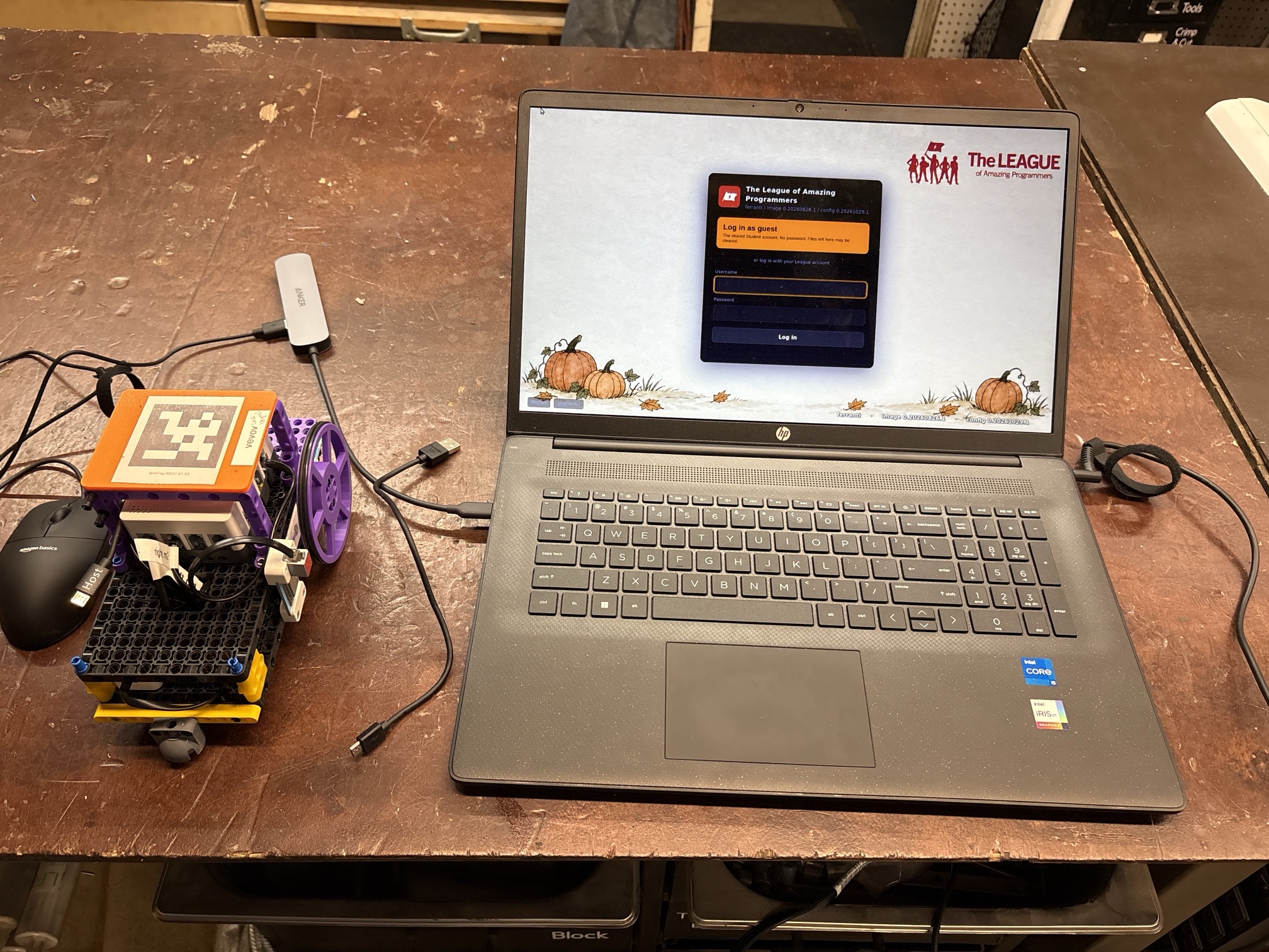
2. Open the robot console
Open the robot console on the laptop. It opens on the Devices page, with a card for each robot it can see.
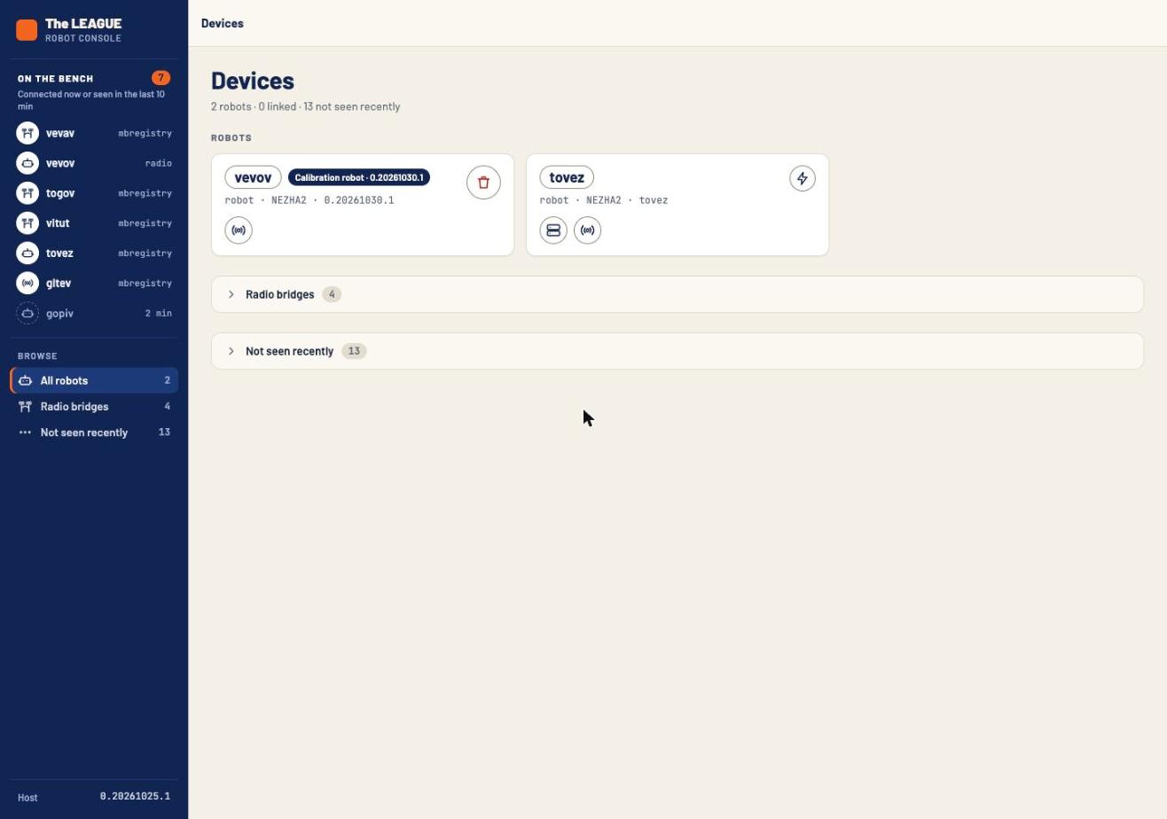
3. Plug in the robot and flash the firmware
Plug the robot into the laptop with the USB cable.
- If this robot has been plugged into the robot console before, it shows up in the list of robots at the top.
- Otherwise it shows up under Unknown devices.
Click the round Flash button in the upper right and flash the robot firmware.
4. Line the robot up on the wheel-measuring mat
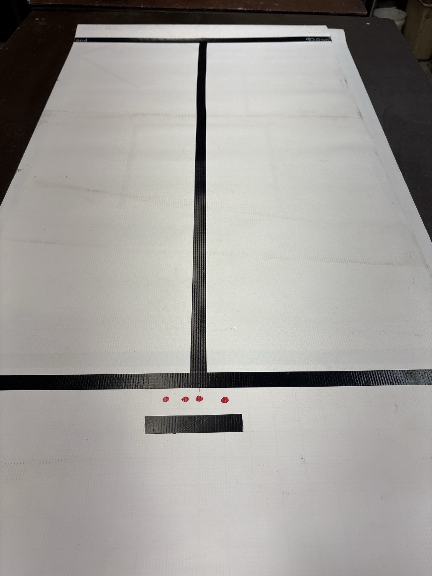
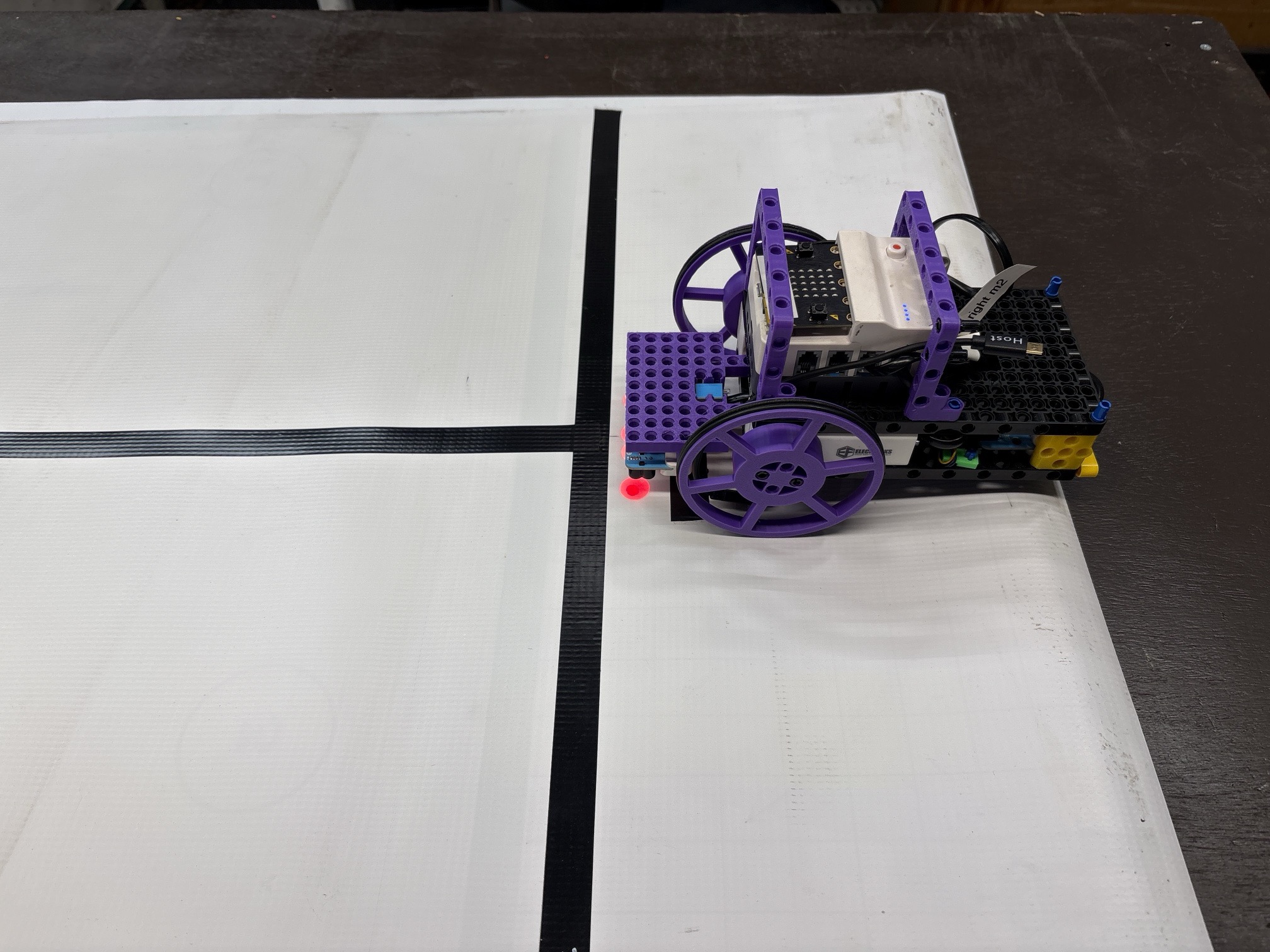
Put your robot on the wheel-measuring mat. Line up the red lights on the robot with the red dots on the mat, so the robot is ready to measure its wheels.
5. Connect to the robot over the radio
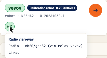
You should be able to start the robot over the radio. In the robot console, click on the radio, find your robot in the list, and click its connection button.
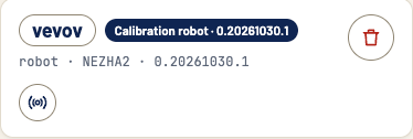
When the robot is linked, its card turns green. Click the orange arrow to open the robot.
6. Calibrate the wheels
Once you’re connected to the robot, go to the Calibration tab.

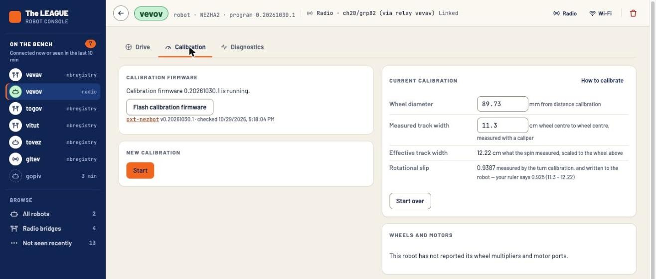
Start a new calibration: press Start under New calibration.

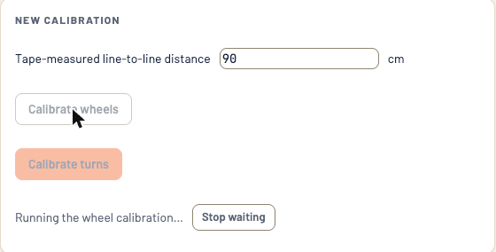
Type in the line-to-line distance on the mat, measured with a tape measure (90 cm in these pictures). The Calibrate wheels and Calibrate turns buttons appear.
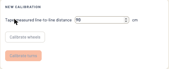
If the buttons stay greyed out, look at the top of the page. The radio link times out when the robot sits idle, and the header then says Not connected. Press Connect to link up again.

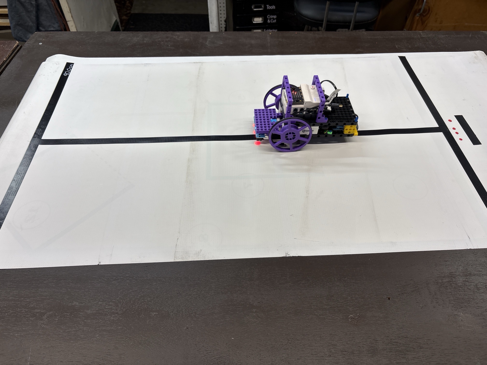
Then calibrate the wheels. The robot should start driving down the center line.
When the robot stops, the console shows the result next to the button.
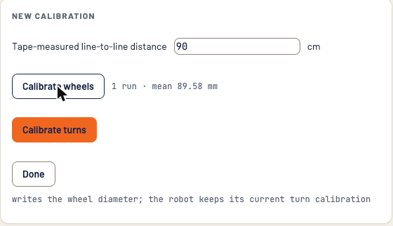
You can run the wheel calibration more than once. Two or three wheel runs will average out any errors in a single run.
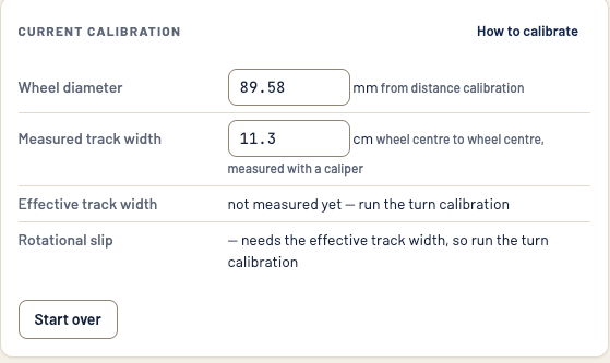
Under Current calibration, the wheel diameter now has its new value. Effective track width stays empty until you calibrate turns.
7. Calibrate turns on the Iron Cross target
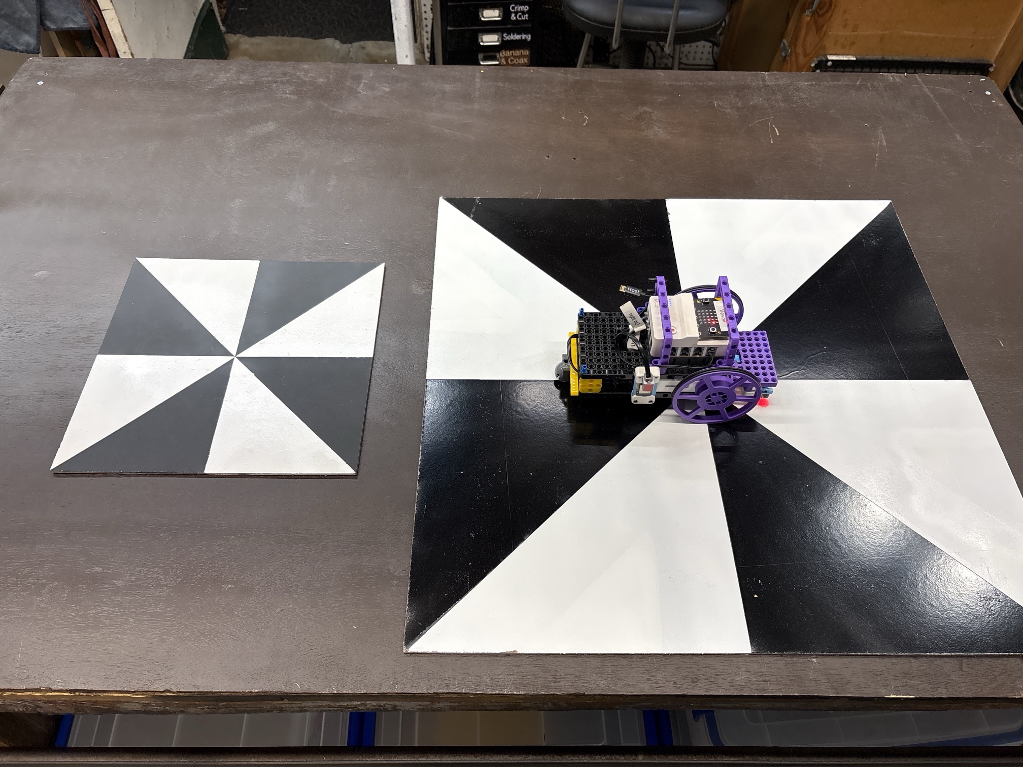
To calibrate turns you need the Iron Cross target. There is a bigger one and a smaller one; pick either, as long as your robot fits on it completely.
Line the robot up on the target:
- The center line of the robot, the line that runs right between the reflectors on the front and the back, goes along one line of the target.
- The axles go along the perpendicular line, so the robot’s center of rotation is right in the middle of the target.
Click the Calibrate Turns button and watch your robot spin around.
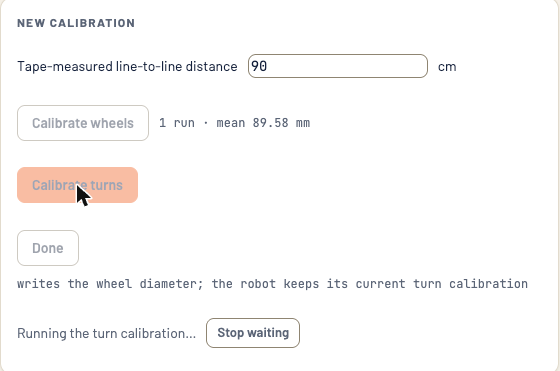
If you run the turn calibration more than once, re-center the robot on the target before each run.
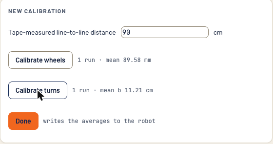
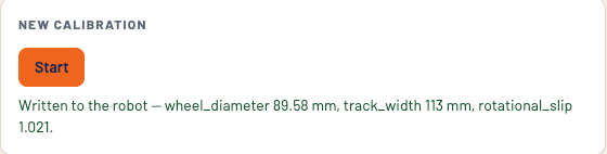
When you’ve finished your runs, press Done. It writes the averages to the robot.
8. Check the calibration values
On the calibration page, look under Current calibration. You now have values for wheel diameter and effective track width.
If you measured the track width yourself with calipers (not covered here), that value shows up too. The most important values are the effective track width and the wheel diameter.
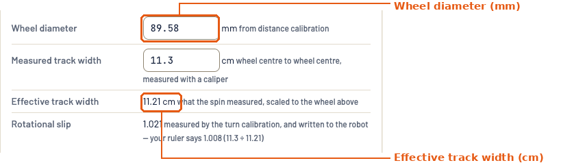
These are the two numbers you need. Write them down; you’ll put them into your program in step 11.
- Wheel diameter, from the wheel calibration, in millimeters: 89.58 mm in this picture.
- Effective track width, from the turn calibration, in centimeters: 11.21 cm in this picture.
Use the effective track width, not the track_width in the message after
Done (113 mm here). That one is the caliper measurement.
9. Open the example program in MakeCode
Now put those values into a program. Start from the example program for the class robot, pxt-nezha-guvug. It’s also listed on the Code page.
- Open MakeCode for micro:bit at https://makecode.microbit.org/.
- On the home page, click Import, then Import URL.
- Paste
https://github.com/League-Robotics/pxt-nezha-guvugand import it.
MakeCode opens the example as a new project of your own, saved in the browser. Changing it doesn’t change the example on GitHub.
10. Rename the project
The example is named Guvug, after a different robot. Click the project name in the box at the bottom of the editor and change it to your robot’s name.
11. Enter your calibration values
In the on start block, find these two blocks and put in the values from the robot console’s Current calibration:
- set wheel perimeter is the distance around the wheel, not the wheel diameter. The console gives the diameter in millimeters, so divide it by 10 to get centimeters, then multiply by π (3.1416). For example, a wheel diameter of 89.58 mm is 8.958 cm, and 8.958 × 3.1416 = 28.14 cm.
- set wheel base is your effective track width. It’s already in centimeters, so put it in as it is: 11.21 cm in the example.
Both blocks are set to centimeters.
12. Flash the program and try it
Plug the robot into the laptop and click Download to flash the program.
- Press B and the robot drives a square, 20 cm on a side. Hold B to stop it after the side it’s on.
- Put the robot on a line and press A and it follows the line. Press A again to stop it.
If the square doesn’t close up, or the corners aren’t square, check the two values you entered in step 11.